

All About Glass & Metals: The Importance of Thermal Bridging
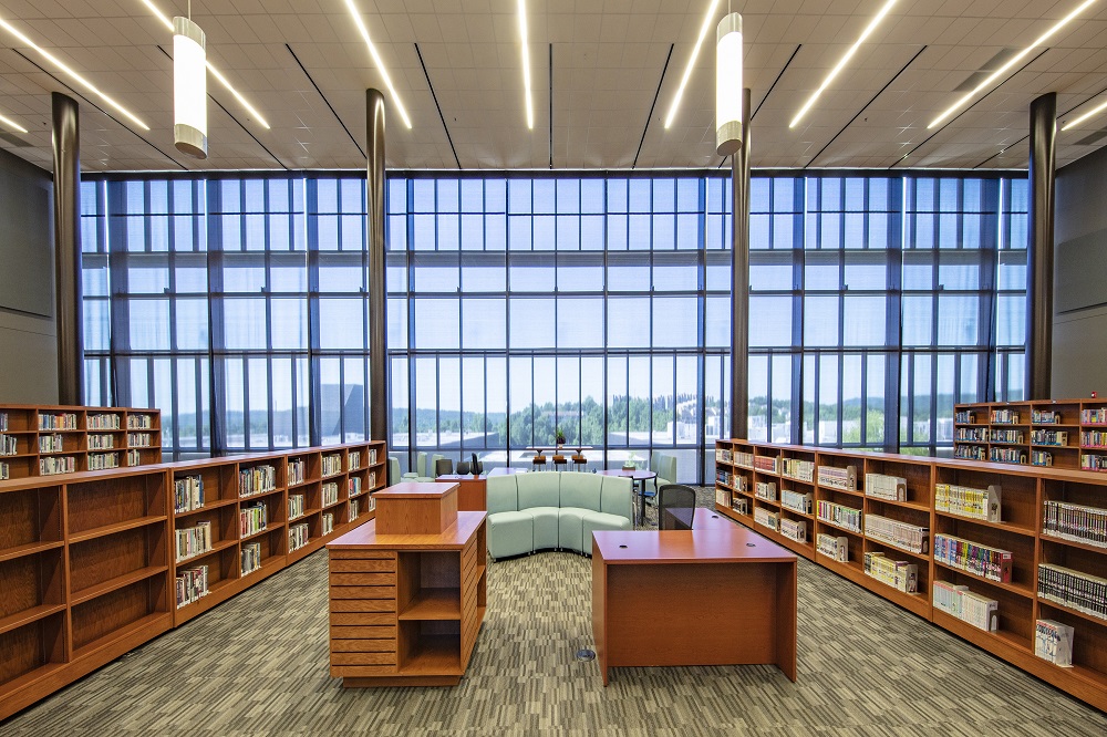
For fenestration assemblies, the potential for thermal bridges may occur where the window framing meets the surrounding wall
Source: Adapted and excerpted from the Thermal Bridging Considerations at Interface Conditions Design Guide, available for download in the NGA Store.
“Thermal bridging is a big deal. It is the silent degrader,” said Helen Sanders, leader in strategic business development for Technoform, during the meeting of the energy group of the NGA Fabricating Committee during the NGA Glass Conference: Long Beach held in January.
Thermal bridging occurs when building exterior cladding or structural components with higher thermal conductivity penetrate or bypass insulation, thus creating a path of least resistance for heat transfer. For example, a steel beam or balcony penetrating the wall insulation will create a path for heat transfer. This pathway could lead to heat loss and decreased energy efficiency as well as potential cold points that can lead to condensation within the building envelope on exposed, interior surfaces.
“We’re not talking about thermal bridging in the frame. That is accounted for with U-factor,” described Tom Culp, owner of Birch Point Consulting, during the conference. “This [is] about how [heat transfer] bypasses insulation in a building. … It’s about alignment between the wall and the windows.”
In wall assemblies, metal penetrations can significantly reduce the effective R-value of the wall insulation. For fenestration assemblies, the potential for thermal bridges may occur where the window framing meets the surrounding wall if the surrounding insulation layer is bypassed.
Thermal bridging in the codes
Model energy codes typically address the performance of individual components in the building envelope. This includes the U-factor and solar heat gain coefficient of fenestration products as well as the R-value of opaque wall construction and roofing assemblies.
Model energy codes typically have not addressed the intersections of these components or penetration of the insulation; however, as they increase in overall stringency, some codes are beginning to address thermal bridging. For example, the Seattle Energy Code increases the amount of continuous insulation required in opaque wall construction based on percent area of metal penetrations compared to a wall with minimal metal penetrations (or thermal bridging). Energy codes in Vancouver and New York City require that thermal bridging details be identified on drawings and be accounted for in all performance modeling.
Most notably, ASHRAE 90.1 has been working on comprehensive new requirements to mitigate thermal bridges in many areas including roof edges, parapets, intermediate wall edges, balconies, masonry shelf angles, and the wall-to-fenestration intersection. These requirements will apply to colder regions (ASHRAE’s climate zones 4-8) and are anticipated to be included in the 2022 edition of ASHRAE 90.1, which will also be referenced in the 2024 International Energy Conservation Code (IECC).
How to account for thermal bridges
The energy codes account for thermal bridges in two ways: simple prescriptive strategies and more complex modeling.
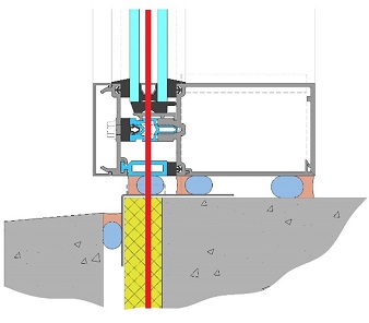
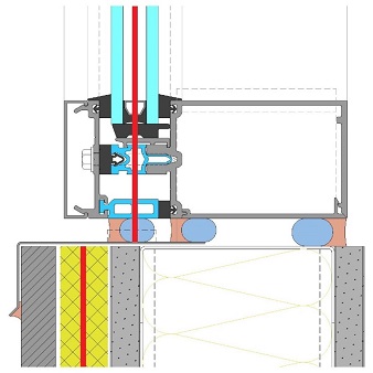
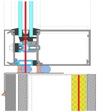
The simple approach can be deduced to a basic concept of a “thermal line” or “thermal plane.” Just as designers and engineers look for a continuous line connecting the constructions to form the primary air and water barriers, they should also now look to construct a continuous thermal line connecting the insulating materials across the transition details from fenestration to surrounding construction to create a “thermal barrier” between components. This results in different simple prescriptive strategies, shown in the diagrams pictured.
Strategies to consider
For fenestration assemblies, whether a punched opening window or a curtain wall, the concept of a “thermal line” leads to the ideal scenario: alignment of the insulating glass units, thermal breaks within the frame, and insulation in surrounding construction without any significant bypasses. This ideal is not always possible when considering the many functional design requirements regarding structural support, water management, etc. However, better alignment will generally result in less thermal heat loss and an improved (lower) psi-factor.
The simplified prescriptive requirements proposed for ASHRAE 90.1 also try to encourage this practice of alignment and/or a continuous thermal line as much as possible. ASHRAE 90.1’s primary requirement is to align the glazing layer within 2 inches of the wall continuous insulation (e.g. mineral wool or insulating foam board), or within 2 inches of the exterior side of the cavity insulation where there is no continuous insulation. Ideally, thermal breaks within the frame are also aligned with the glazing, and the benefit from doing so will be reflected in the lower U-factor rating for the product.
Aligning the glazing system and the wall insulation is not always possible because of functional considerations such as structural design or simply for design aesthetics. Therefore, ASHRAE 90.1 also includes other options for recessed windows or offset construction. In that case, the goal is to continue the thermal line from the continuous insulation to the window framing, covering any exposed area with insulating material with R-value greater than 3 or thermal conductivity less than 3.0 Btu·in/h·ft2·°F (this would also include the option to mount the fenestration within a wood buck). It is not required that the insulation be under the frame, as careful consideration must be given to the attachment and support of the window, as well as proper water drainage.
In all cases, the intent is to maintain a continuous thermal line, as much as possible, to minimize interruption of the thermal line, thus creating “thermally bridged” details. However, there are many other issues that must also be considered at the same time.
More from the design guide
Consult the Thermal Bridging Considerations at Interface Conditions Design Guide for definitions of the two thermal bridging characterizations, linear and point; a breakdown of complex thermal bridging modeling; diagrams and photography depicting thermal bridging concepts; and strategies for edges and perimeters. The guide also explores the responsibility of designers to indicate thermal lines in construction drawings, and the responsibility of fenestration industry companies to provide an overall energy rating for a glazing system.
Task group members
The design guide was developed by the following task group volunteers:
- Technical Glass Products (Chuck Knickerbocker, chair)
- AGC Interpane (Steve Dean)
- Allstar Glass Company LLC (Nathan Breazile)
- Birch Point Consulting LLC (Tom Culp)
- dormakaba (Meagan Lang)
- Dow (Stanley Yee)
- Giroux Glass Inc. (Gregory Wright)
- Heartland Glass (Garrity Gerber)
- Intertek (Ted Derby)
- Jones Paint and Glass (Brian Clark)
- Kawneer North America (Chris Giovannielli, Sneh Kumar, Greg McKenna, Henry Taylor, Ivan Zuniga)
- Mesko Glass & Mirror (George Mesko)
- Oldcastle BuildingEnvelope (Ben West, Rick Wright)
- St. Germain’s Glass (Mike McCabe)
- Steel Encounters (Derek Losee)
- Viracon (Aaron Thompson, Fabricating Committee chair)
- Wausau Window & Wall Systems (Steve Fronek)
- Woodbridge Glass (Matt Kamper)