Thermal Bridging Considerations at Interface Conditions
Thermal bridging occurs when building exterior cladding or structural components with higher thermal conductivity penetrate or bypass insulation, creating a path of least resistance for heat transfer.
What is thermal bridging?
Thermal bridges are localized areas of high heat flow through walls, roofs and other insulated building envelope components. Thermal bridging is caused by highly conductive elements that penetrate the thermal insulation and/or misaligned planes of thermal insulation. These paths allow heat flow to bypass the insulating layer and reduce the effectiveness of the insulation.
Why does thermal bridging matter?
Building envelope thermal performance is a critical consideration for reducing space heating loads and will be an increasingly important factor as model energy codes strive for lower energy consumption in buildings. Thermal bridges allow uncontrolled heat flow to bypass the envelope insulating layer introducing uncertainty of thermal performance and enhance the risk of inefficient design. Most notably, ASHRAE 90.1 has requirements to mitigate thermal bridges in many areas, including roof edges, parapets, intermediate wall edges, balconies, masonry shelf angles and the wall-to-fenestration intersection. These requirements apply to colder regions (ASHRAE’s climate zones 4-8) and are included in the 2022 edition of ASHRAE 90.1, which is referenced in the 2024 International Energy Conservation Code. The energy codes account for thermal bridges in two ways: simple prescriptive strategies and more complex modeling.
Simple approach to account for thermal bridging
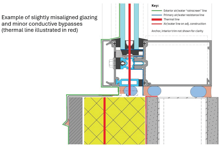
The simple approach can be deduced to a basic concept of a “thermal line” or “thermal plane.” When looking at details at the window/wall interface, many designers are accustomed to the idea of drawing and looking for a continuous water control line and air leakage control line. The same concept can be applied to thermal bridging, by looking for a continuous thermal line. The architectural drawings typically represent the vision of the design team for the exterior cladding. Most notably, the elevations and sections indicate where the glazing system framing members are to be located, the size and type of glazing infills, etc. While everyone, from architect to glazing subcontractor, recognizes the information conveyed in typical vertical and horizontal section cuts through the glazing systems, it’s critical the perimeter details indicate the proximity and relationship of the glazing system to the air- and water-barrier locations in or on the adjacent construction, and how any anchorage details, sealant joints and other components may interact or impact the glazing system. The glazing subcontractor and framing manufacturer should be able to determine how water can be drained from the glazing system to the building exterior. Establishment of the air-barrier transition from fenestration system to perimeter conditions is equally important.
For fenestration assemblies, whether a punched opening window or a curtain wall, the concept of a “thermal line” leads to the ideal scenario: alignment of the insulating glass units, thermal breaks within the frame, and insulation in surrounding construction without any significant bypasses. This ideal is not always possible when considering the many functional design requirements regarding structural support, water management, aesthetics, etc. However, better alignment will generally result in less thermal heat loss.
Complex approach to account for thermal bridging
The more complex approach involves comprehensive heat transfer modeling of assembly details at each interface. This modeling generates psi- and chi-factor thermal transmittance numbers for each construction detail. Linear thermal bridges (such as balconies, shelf angles or fenestration framing where the installation bypasses the wall insulation) are characterized by psi-factor, ψ, which is the thermal transmittance-per-unit length in units of Btu/(h·ft·°F) or W/m·K. Point thermal bridges (such as localized penetrations of beams, columns or anchors where the installation bypasses the wall insulation) are characterized by chi-factor, χ, which is the thermal transmittance-per-penetration area in units of Btu/(h·°F) or W/K. These numbers can be used to adjust the effective U-factor of the envelope assembly and to account for the greater heat loss in whole building performance calculations. Psi- and chi-factors can either be modeled for each custom assembly detail, or pre-calculated and provided for common constructions. These values would be necessary if using the performance path of building energy codes for compliance.
Other considerations at edges and perimeters
While a drawing of a detail is “static,” the actual construction of that joint is not. It is often a dynamic joint and should be detailed and executed with that in mind. In addition to the “thermally bridged” details, consider how to accommodate movement, water weeping, insulation, and cost-effectiveness.
Architect resources
NGA is an approved AIA Provider and, thanks to the involvement of its volunteer members, has nine approved industry-consensus presentations available. Members may use these presentations when reaching out to architects and other interested parties.
Volunteer task group
NGA thanks our task group volunteers for developing this resource: Stanley Yee–chair; Darin Clifton, Corte Consulting; Ted Derby, Intertek; Sam Olson, J & A Glass Inc.; Chris Schultz and Henry Taylor, Kawneer; Cliff Anderson and Jose Rodriguez, Oldcastle BuildingEnvelope; Adam Funk, Premier Glass; Helen Sanders, Technoform North America; Chuck Knickerbocker, Technical Glass Products (Allegion); Matt Kamper, Woodbridge Glass Inc.; Ivan Zuniga, YKK AP America Inc.; Tom Culp, Birch Point Consulting LLC and NGA energy code consultant. We would also like to thank Dow for their contribution.