Unitized Curtain Walls and Their Limitations
Addressing challenges with alignment, end dam reliability and thermal bridging
Unitized curtain walls have become the preferred method for enclosing buildings, as more building owners, architects and contractors see the benefits of this type of construction. Unitized systems allow buildings to be enclosed quickly, which can help to speed up the construction process leading to earlier occupation. The fabrication process for unitized systems is more consistent than for stick-built curtain walls, as unitized wall systems are constructed in almost an assembly line fashion, indoors, and under controlled environmental conditions.
However, as with any type of construction product, the more the systems are used, the more we begin to understand their limitations. This article addresses three common limitations and problems that are encountered with the use of unitized curtain walls, along with considerations for addressing such problems. Since unitized curtain walls are the current state-of-the-art in curtain wall technology, designers, consultants and contractors alike need to become familiar with these systems’ technical limitations, so that we can develop effective designs that address their use for all areas of the building enclosure.
Alignment
There are two types of alignment conditions that must be considered with unitized curtain wall construction:
- Alignment between unitized panels
- Alignment between unitized panels and projecting slabs, canopies and other offsetting structural features of a building.
Curtain wall manufacturers have reliably dealt with the issue of panel-to-panel alignment by developing structural alignment clips that can be slid across the interlocking heads of adjoining panels to maintain horizontal alignment (Figure 1), and by refining the designs of their lifting lugs that help to hold the vertical alignment between panels at their stack conditions (Figure 2). The alignment challenges that manufacturers now face are the unique project-specific building features that interfere with typical panel alignments and must be dealt with on a project-by-project basis.
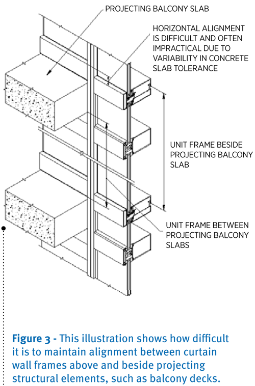
This problem with panel alignment principally occurs with new construction. Unitized curtain walls are generally fabricated concurrently with the erection of steel and concrete building frames and slabs. Since structural frames and curtain wall fabrication typically hold to different tolerance levels, unitized curtain walls may not always fit within the space that is allotted for them on paper. Curtain wall frame fabrication is typically held to a much tighter tolerance than steel and concrete construction. While curtain walls are generally held to fabrication tolerances of +/-V inch, steel and concrete erection tolerances may be as much as +/- 1 inch. It is this variation in tolerance that can begin to challenge unitized curtain wall erection (Figure 3).
Contractors are also challenged by the fact that floor slabs tend to deflect between support conditions.
Given this, a unitized frame may not fit beneath a projecting floor slab or even between two projecting balconies. This situation will arise if, for example, one balcony is up from its design datum by 1 inch and the balcony immediately above is down 1 inch from its design datum.
It is impractical to expect that the erection of projecting structural elements can be held to much tighter tolerances. Thus, the more realistic approach is to recognize these inevitable conflicts and design around them.
A solution to this problem should never be to modify unitized frames in the field, or to cut away portions of the concrete slab or other structural element in order to accommodate structural misalignments and normal building deflections. The solution is to design around these inevitable conditions rather than react to a problem after it occurs.
The most practical and cost effective means for dealing with varying structural conditions is to incorporate a “leave out” panel above the unitized wall that can be custom measured and fabricated after the curtain wall is installed in the building (Figure 4).
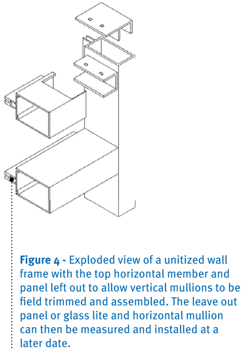
If the design cannot tolerate a customized wall infill panel and must be installed, for instance, with glass or shadow box in-fills to match the unitized wall beyond the extents of a balcony slab, then these components must also be left out of the unitized wall frames. This includes the topmost horizontal member of the unit wall beneath the projection. In such situations, the individual glass or shadow box in-fills must be measured, field sized and installed with the top horizontal member at a later date. This process requires field-cutting vertical mullions that are left long from fabrication. It violates the idea that you should not have to modify a frame in the field, and is a deviation from the intent of true unitized wall construction. Nonetheless, we do recognize it as an alternative means for addressing conflicts with projecting structural elements.
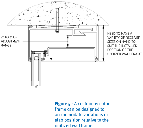
A second means for addressing curtain wall-to-structure alignment conditions is to develop a design utilizing a deep receptor frame, possibly with a bite range of 2 to 3 inches (Figure 5) to accommodate large tolerance variations in structural interference. This is the least reliable method for dealing with misalignment issues, as it cannot accommodate every conceivable misalignment situation and can begin to get bulky and unwieldy in appearance.
Unitized wall end dams
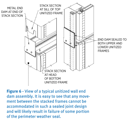
Unitized curtain walls will require end dams whenever the curtain wall will terminate against another wall system. If a building design only incorporates curtain wall, then end dams will not be required. Typically, unitized curtain wall manufacturers will incorporate an end dam composed of a metal end cap that is mechanically attached and sealed to the end of the stack section of the curtain wall, which in turn is adhered to the unit frame that is stacked above, similar to what is shown in Figure 6. Once the perimeter seals and corner seals between the end dam and frame above are installed, the ability of the system to accommodate differential movement is hampered, as the two modular units become locked together with sealant. Differential movement between two stacked units will not be resisted by the end dam seals, and the likely result will be failure of the perimeter seal or failure of the end dam seal, each of which may result in air and/or water infiltration into the building.
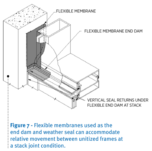
Using a flexible membrane flashing, similar to the silicone sheet utilized by curtain wall manufacturers for joining unit frame intersections at the stack condition, creates a more flexible and reliable end dam seal compared to the typical metal end dam. Figure 7 shows one concept for what a flexible unit end dam detail may look like terminating against a concrete wall. In our example, we incorporate two lines of protection at the concrete interface. We still can utilize the metal end dam as is standard practice for the curtain wall manufacturer, but we maintain separation by not sealing the end dam to the stacked unit above. Thus, we maintain an effective air and weather seal without sealing the two stack units together.
Thermal bridging at the stack head
Most manufacturers’ stacking designs do not incorporate thermal breaks, even though other horizontal and vertical members within the unitized wall frame may be thermally broken. This causes the frame to be cooled through the depth of the stack section, which increases the potential for condensation to form on the inboard side of the frame which in turn can stain or damage interior finishes.
Stack sections are not typically thermally broken because the stack head must be able to resist rotation from positive and negative wind loads, and be able to transfer sometimes large loads through the stack to the unitized frame below. Since thermal breaks are composed of either plastic or vinyl composites, they have lower strength capacity than solid aluminum framing and cannot always be relied upon to transmit structural loads between unit frames.
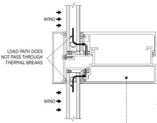
To establish a working stack design that incorporates a thermal break requires that the load path be routed through the frame around the thermal break and not through the thermal break only. Since thermal breaks are most effective when they align with the insulating glass units, they would typically be positioned within the horizontal legs of the frame outboard of the stacking head. One method for including a thermal break in the stack design is to incorporate structural seals in the frame design as shown in Figure 8, and not to utilize a dry glazing system. When glass is structurally glazed in a unitized frame, wind loads (both positive and negative) are carried through the structural sealant and into the frame directly, instead of being routed through the exterior stops and thermal breaks.
